Contribute
| Technology - Methodology To Develop Machine Accuracy |
Barish R. Dantal
09/24/2004
(This article is sponsored by The Boston Group)
INTRODUCTION
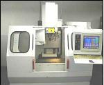
The main objective of the project is to develop a general methodology to predict combined error (resulting from the errors of the individual elements of the machine tool structure) in the position of the cutting tool with respect to work piece. Machine under study is, as shown in picture, three axes Bridgeport Discovery 308 vertical milling machine. All-important factors affecting the accuracy of the final position of the cutting tool relative to the work piece are included in the model.
All the six degrees of freedom are used to define the position of a rigid body with respect to another. Errors in each of the six degrees of freedom may have numerous contributing components. Mathematical model is used to keep track of and allocate allowable values of the errors among different components of machines. Geometric errors in machine occur in all three axes and are composed of three translational and three rotational components per axis. In addition there is an error associated with the squareness of the axes with respect to each other. Altogether, this causes twenty-one sources of geometric error in the machine.
All these errors were measured by using Laser Interferometer, Ball Bar and Electronic Level to make a map of the geometric errors within the structure. This mapping did not include temperature effects and therefore machine was brought into an equilibrium state in its environment before being error-mapped. There are other sources of errors; in this study we only considered geometric errors in machine.
A mathematical model is designed on the basis of connectivity rules that define the behavior of machine’s components and their interfaces, and combinational rules that describe how errors of different types are to be combined.
EXPERIMENTAL STUDY AND RESULTS
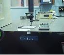
Laser Interferometer System is used to measure five simultaneous measurements. These include linear displacement, horizontal straightness, vertical straightness, yaw, and pitch.
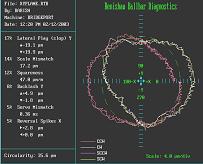
Ballbar Test is conducted to measure squareness error of axis. Ballbar test also gives good picture about scale mismatch, lateral display and backlash of axes. The actual radius of a tool path is used to calibrate the ball bar. Ballbar test produce results as shown in pictures.
Electronic Level Gage Kit is ideal for on-the-fly measurement of way alignment using profile, profile parallelism, flatness, or surface parallelism tests. This kit is used to easily check machine geometry deformation due to changes in temperature stratification. Roll error is measured for x and y axes.
MATHEMATICAL MODEL
The main purpose of the study is to find an expression that describes the xyz error at the tool tip as a function of i) tool length, ii) x, y, z position in the machine working volume and iii) the measured parametric errors, namely, translations and rotations.
With the help of vector calculation following error equation for each axis is obtained.


ERROR CALCULATION
Error in each axis is calculated by the data collected from various test results. Data is stored in spreadsheet. To calculate error along x at any point in the working volume a user needs to enter the values of x, y and z coordinate, tool length, and values of straightness error along three axes. All errors are linked to the test intervals. When user enters the value of x, y and z coordinate’s software uses look up function to get the value for that interval. All the errors are collected in same manner. They are then finally put into an equation to calculate the error along axis. In final spreadsheet, the user can enter the required data to calculate total errors along x, y and z-axis. Macro programming is done to calculate error at any point in the working volume. So when a user enters the basic data all calculations are done within the spreadsheet and the test results displayed.
CONCLUSIONS
Comparison of errors predicted by the mathematical model (based on average values) developed with the test results from CMM measurements is tabulated. The predictions from mathematical model are corrected for the spread in measurements. It is clear that the corrections made on account of dispersions from the mean value gives a better agreement between the predicted and measured results. In future work, to improve results obtained from the mathematical model, which gives closer results to those, obtained from the CMM some factors are need to be added. Some of the factors such as, non-systematic error, CMM measurement uncertainty, spindle alignment with Z-axis, concentricity of the spindle, and tool run out have not been included in the model because of lack of data. The inclusion of these effects would bring the measurement to a more realistic comparison of error prediction data with CMM results.
REFERENCES
“Precision Machine Design” by Slocum A.H, (Society of Manufacturing Engineers, January 1992)
“Accuracy of Machine Tools” by Reshetov .D.N, Dunaesky .V.V, Portman.V.T (ASME Press)
“A Displacement Method for Machine Geometry Calibration”, Zhang. G, (1), Ouyang R., Lu B.; Tianjin University/PRC; R.Hocken (1), Veale R., Donmez A.; National Bureau of Standards /USA, January 18, 1988, Annals of the CIRP vol. 37/1, 1988
“Error Compensation of Coordinate Measuring Machines”, Zhang G, Tianjin University /PRC, Veale R, Charlton T, Borchardt B and Hocken R (2), National Bureau of Standards, Gaitherburg MD 20899, Annals of the CIRP vol. 34/1, 1985
“Three Dimensional Metrology”, Hocken R, Simpson J.A, Borchardt B, Lazar J, Reeve C, and Stein P, NBS, Washington D.C., Annals of the CIRP vol. 26/2,1977, www.renishaw.com, www.apisensor.com.
You may also access this article through our web-site http://www.lokvani.com/